Takeaways
- The acquisition and analysis of radiographs for morphometric measurements are prone to failure if technical standards aren’t considered.
- Defined protocols must be respected to obtain comparable images and correct measurements.
- As a reference for trimming and shoeing, one measurement of the joint space symmetry in one single radiograph is probably not reliable enough to judge toe conformation.
Radiological and radiographic examinations are frequently performed in equine practices. The difference between both techniques are their use and aim.
Radiology is a medical specialty that uses X-rays as an imaging technique to diagnose diseases and guide their treatment. In the clinical context, radiological examination is a diagnostic tool and is mainly performed to discover pathologies of bones, joints or connected structures and monitor the progress of healing or degenerative diseases.
In contrast, radiographic examinations use X-rays for measurements to evaluate their conformation and take morphometric parameters as a reference for further treatments. Radiographic measurements are widely used to assess morphometric parameters for evaluation of hoof conformation and as a basis for trimming and shoeing protocols.
Objective assessment of geometric hoof balance with the use of radiographic hoof measurements and quantitative description of the position of the digital bones in relation to the hoof capsule have been proposed to achieve ideal trimming for an individual horse’s conformation.
Radiographic Measurements
Typical parameters assessed with radiographic examinations at the equine foot as a reference for farriery (Figure 1) are (Caudron et al., 1998; Rocha et al., 2004; Kummer et al., 2006):
- Hoof-pastern axis.
- Toe axis.
- Joint space symmetry of the digital joints.
- Sole depth.
- Distal phalanx position.
• Distance between extensor process and the coronary band.
• Distance between the apex of the distal phalanx and the apex of the hoof.
• Mediolateral orientation of the distal phalanx. - Parallelism between dorsal hoof wall and dorsal surface of the distal phalanx.
- Palmar angle of the distal phalanx to the ground.
- Mediolateral angle of the distal phalanx to the ground.

FIGURE 1: The morphometric parameters of the equine foot are the hoof-pastern axis, toe axis, joint space symmetry of the digital joints, sole depth, position of the distal phalanx, parallelism between dorsal hoof wall and dorsal surface of the distal phalanx, palmar angle of the distal phalanx to the ground and mediolateral angle of the distal phalanx to the ground. Dr. Jenny Hagen
Acquiring radiographs of the foot in different perspectives allows measurement of dimensions and angles of the equine phalanges (Caudron et al., 1998; Rocha et al., 2004; Cripps et al., 1999). In addition, the use of radiopaque markers provides the possibility to visualize borders of the equine hoof capsule and calculate morphometric parameters. Thereby, angles and shape of the hoof capsule can be correlated with the position and dimensions of the distal phalanx (Page, 2001; Dyson et al., 2011).
Functional conclusions can be drawn from these analyses with regard to (a)symmetries, phalangeal alignment, breakover, size of supporting surface, rotation centers of the digital joints and acting moment arms (Hagen et al., 2016; Hüppler et al., 2016; Hagen et al., 2018; Kummer et al., 1997). Due to the wide range of morphometric parameters of the equine toe, which can be assessed by radiographic examination, this technique is frequently used to evaluate the foot conformation, to use the information as a reference for farriery and to evaluate the effect of trimming and shoeing (Hagen et al., 2016; Hüppler et al., 2016; Hagen et al., 2018; Kummer et al., 1997; Hagen et al., 2017).
In addition, radiographic measurements were used quite often in research to evaluate the effect of trimming or shoeing on the toe alignment and the position of the distal phalanx inside the hoof capsule. The use of a standardized protocol to acquire radiographs in combination with the use of the examination software, such as MetronPX, to analyze the images has been evaluated to provide sufficient reliability (Roch et al., 2004).
Reliability of Radiographic Measurements
The technique’s advantage is it provides insights into the foot that are not visible by the usual clinic examination. Moreover, radiographic measurements of the equine foot enable an objective evaluation of the toe conformation. In general, the evaluation of the limb and toe conformation is prone to bias and of subjective character. An objective analysis of the foot is the basis for the investigation of the effect of trimming or shoeing on the hoof conformation. Still, the acquisition and analysis of radiographs for morphometric measurements is prone to failures if necessary technical standards and protocols are not considered.
Quantitative (comparative) radiographic measurements (for example, comparing the hoof before and after trimming) require a highly-standardized image acquisition and analysis. Defined protocols must be respected to obtain comparable images and correct measurements (Kummer et al., 2006). Yet, radiographs often fail in relation to projection obliquity and distortion (Kummer et al., 2006; Koblik et al., 1988).
Another limitation is that radiographs represent a static snapshot of a dynamic situation (Hüppler et al., 2016; Hagen et al., 2018). The load of the limb and the position of the foot during the examination have a valuable impact on the angulation of the phalanges (Pauwels et al., 2017; Contino et al., 2014). In summary, the reliability of radiographic examinations is affected by the following factors:
- Technical set-up and standard (Baxter, 2011).
- Positioning of the horse (Pauwels et al., 2017; Contino et al., 2014).
- Load of the limb.
- Experience and skill of the operator (Rocha et al., 2004).
- Radiograph quality (Neves, 1999).
- Foot conformation and bone irregularities (Rocha et al., 2004).
- Software measuring errors (Rocha et al., 2004).
In the following, the most important factors that influence morphometric measurements at the equine foot shall be explained.
Well-described protocols need to be considered to create valuable, high-quality radiographs. It’s necessary that a defined object-camera distance is maintained, and reference marks are required to guarantee proper orientation of the cameras and calculate the accurate distances in the X-ray image.
To assess standardized lateral images of the toe, Dyson et al. (2011) used a point midway between the dorsal and palmar aspects of the coronary band at a standard distance of 0.75 m for centering the camera. White et al. (2008) visually aligned the heel bulbs when creating lateral radiographs of the equine toe.
“The measured joint space symmetry showed 10 different values…”
Furthermore, standardized settings have to be maintained during repeat radiographic examination (Neves, 1999). Besides the exposure factor (kV) and exposure time (mAs) the film-focus and the film-object distance must be equal for all examinations (Rocha et al., 2004). Kummer et al. (2006) developed a modified podoblock with a holder for the X-ray plate and the tube at a defined distance from the foot and rotatable around the limb during examination to create images from different perspectives (Kummer et al., 1997). However, modern X-ray technique does provide sufficient technical features to keep the same distance between object and camera for comparative radiographic measurements.
In addition, the analyses of the radiographs must be accurate, precise and comparable. Therefore, calibration tools or reference marks in the podoblocks are necessary for subsequent calibration and measurements of lengths and angles (Kummer et al., 2006).
MetronPX software is frequently used for radiographic or photographic measurements. Rocha et al. (2004) evaluated the accuracy of radiographic measurements of various morphometric parameters of the equine foot measured with MetronPX. The study results evaluated the software as a useful tool to objectively measure most of the predefined parameters. The minimal variation in the measured parameters analyzed by the same operator indicates sufficient repeatability of most values assessed with this software. Using this study, differences among the quantitative measurements with MetronPX are not considered clinically relevant.
Defining Reference Lines & Points
However, avoiding projection obliquity and distortion is a challenge. It’s particularly difficult to provide the same X-ray beam angle and spot between repetitive imaging. The beam’s center must be at the same spot and angle for quantitative measurements. Therefore, it’s necessary to define reference lines and points and mark the center of the beam on the foot.
Typical foot examinations are lateromedial and dorsopalmar, as well as solar projections and skyline images. For lateromedial projections, a line in the widest part of the hoof is extended in the orientation of the horn tubules to the coronary band to define the optimal spot for centering the X-ray beam (Figure 2) (Rocha et al., 2004; Kummer et al., 2006). In the dorsopalmar projection, a line crossing the central sulcus and the tip of the frog through the middle of the dorsal hoof wall extended in the orientation of the horn tubules to the coronary band is used to mark the right spot (Figure 2) (Caudron et al., 1998). The beam can be focused at different heights on this line. The height of the beam varies depending on the intent.

FIGURE 2: The reference lines for marking reference points for centering the X-ray beam.
To demonstrate the distal margin of the distal phalanx to show the exact position of the bone, the beam should be centered on the hoof’s weight-bearing margin (Hagen et al., 2016; Hagen et al., 2017). This is slightly different from the standard overview radiograph of the equine toe to examine it for pathological changes of bones and joints of the toe. For this aim, the X-ray beam is usually centered around the coronary band to create valuable images of all digital joints.
To demonstrate the proximal phalanx or the metacarpophalangeal joint, the beam must be centered as close as possible to the region of interest (Baxter, 2011). For visualization of the distal phalanx, it’s more useful to center the X-ray beam at the weight-bearing margin or 1-2 cm above. This height shows the sole depth and the distal margin of the distal phalanx without projection obliquity.
“A 5 cm abduction of the limb causes a significant difference in coffin joint space symmetry…”
In comparison, keeping a standardized X-ray beam angle for quantitative measurements is more difficult.
The author’s examinations of cadaver limbs show the importance of projection obliquity on the reliability of radiographs for comparative, morphometric measurements. Ten cadaver limbs were standardized and tightly fixed at a podoblock. The X-ray camera was attached to a mobile stand in a defined height (Figure 3). With a caliper, the projection angle was measured and changed stepwise.

FIGURE 3: The technical set-up to examine the effect of a change of projection angle on the quality of radiographs.
Foot radiographs were taken in a 0-degree projection and from 5, 10, 15 and 20 degrees to the left and right from the object in this set-up. The same procedure was repeated for the 90-degree projection with 5-, 10-, 15- and 20-degree angle change in both directions. (Figure 4).

FIGURE 4: The gradual change of the projection angle to assess its effect on the quality of radiographs.
Radiograph quality with regard to the correct projection (0 or 90 degrees) was evaluated based on some published standards. In the 0-degree projection, the frog’s central groove, the extensor process and half the distance between both condyles of the middle and proximal phalanx must be in line. The solar margin of the distal phalanx and the digital joint spaces must be clearly definable (Rocha et al., 2004). Dyson et al. (2011) stated the following demands on a good image in the lateromedial projection.
- The condyles of the middle and proximal phalanx are parallel and no more than 5 mm apart at any point.
- The lateral and medial distal borders of the distal phalanx are superimposed.
- The palmar aspects of the extensor process are superimposed.
- The interphalangeal joint spaces have to appear clearly.
Subsequently, the distal interphalangeal joint (DIPJ) space symmetry, the mediolateral angle of the distal and middle phalanx to the bottom and the palmar angle of the distal phalanx were analyzed in each radiograph with MetronPX. For both projections, it was shown that angle changes of 5-10 degrees made a difference in the occurrence of the structures in the radiograph and on the measured values of all parameters (Figures 5a & 5b). Therefore, this failure must be considered for comparing morphometric toe parameters before and after trimming or shoeing. It’s often very difficult to create repetitive radiographs in the same angle.

FIGURE 5a: The occurrence of the bone structures of the same foot with a gradual change of the projection angle in the 0-degree projection.

FIGURE 5b: The occurrence of the bone structures of the same foot with a gradual change of the projection angle in the 90-degree projection.
Another important factor affecting radiograph quality is correct and reproducible positioning of the horse and limbs (Pauwels et al., 2017; Contino et al., 2014). The importance of the technical set-up standardization and positioning increase when long-term studies or quantitative examinations to assess how different factors affect hoof morphology are performed (Hagen et al., 2016; Hüppler et al., 2016; Hagen et al., 2018; Hagen et al., 2017). Optimally, horses stand calm, square, straight and bear even weight on a plane surface or on podoblocks.
Using Podoblocks
It’s crucial to elevate the foot with a podoblock when acquiring images of the whole hoof, including its distal border. Depending on the size of the X-ray tube, the blocks should be 5-10 cm high. The horse must stand square and relaxed in its natural position (Caudron et al., 1998).
To achieve this, the examined foot was placed on a podoblock with an included axle bearing, allowing a rotation of the individual posture and limb conformation. Recommendations conflict over whether the contralateral limb should be elevated (Hüppler et al., 2016; Crevier-
Denoix et al., 2001). In the author’s opinion, it’s more physiological and ideal to assess natural foot conformation to enable even weight bearing between both fore or hind limbs by positioning them at the same height. To allow more freedom for positioning the unexamined limb, it can be useful to place it on a wide board in its natural position to the contralateral limb, which is placed on the examination block (Figure 6).

FIGURE 6: Positioning the limbs on an equal height and with enough space to enable a physiological limb position.
In particular, limb positioning must significantly influence the appearance and accurate calculation of the digital joint spaces (Contino et al., 2014). The higher the degree of limb abduction, the narrower the medial and the wider the lateral aspect of the joints become. My studies and examinations of Contino et al., 2014, showed that a 5 cm limb abduction causes a significant difference in DIPJ space symmetry (Figure 7). This can lead to radiograph misinterpretation of the conformation and toe load.

FIGURE 7: The effect of limb abduction on the joint space symmetry.
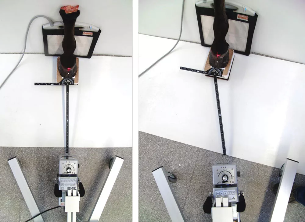
The same is valid for the 90-degree projection to assess hoof-pastern axis straightness. Just 5 cm dorsal or palmar limb placement causes significant difference in deviations (Figure 8). Alone, this source of failure makes the use of a single radiograph to measure the joint space symmetry and the pastern axis as a reference for trimming doubtful. If this parameter is used as a reference, the obtained results should be judged in the context of the visually assessed hoof and limb conformation.

FIGURE 8: The effect of limb placement on the pastern axis.
This is enhanced by another examination’s results. The position of the X-ray block, camera stand and film cassette were marked on the ground. The podoblock, board for the unexamined limb and camera stand were fixed to the bottom. The film cassette was repositioned for each radiograph at a marked position behind the podoblock.
Subsequently, a horse was positioned at the block and the board and a 0-degree radiograph of the limb was taken. After, the horse was removed and repositioned and the next radiograph was created without moving the set-up. This procedure was repeated 10 times. The DIPJ space symmetry was measured in each image. Although the horse was optimally placed and in the same set-up, the measured joint space symmetry showed 10 different values with deviations of more than 3 degrees between the images (Figure 9).

FIGURE 9: The change of joint space symmetry in repetitive imaging of the toe of one horse standing calm, in a straight body axis on fixed podoblocks with a fixed technical set-up.
Due to these findings, the joint space symmetry examination might provide some valuable information for severe limb deviations. But as a reference for trimming and shoeing, one measurement of the joint space symmetry in one radiograph is probably not reliable enough to judge the toe conformation. The snap-shot character of this technique decreases the measurement value of such a load-dependent parameter.
Another factor involving the distal phalanx position measurability is the hoof conformation and bone irregularities. It could be shown that the distal margin of the distal phalanx in the 0-degree projection is represented more clearly with an accurate (low) hoof angle since less bone material in the distal margin is superimposing each other (Figure 10). In steep hooves, the distal margin of the distal phalanx isn’t as clearly defined. In addition, in feet with broken hoof-toe axis or rotational deviations, it’s difficult to align the structures in one image. Several radiographs are necessary to represent them.

FIGURE 10: The effect of hoof conformation on the occurrence of the distal margin of the distal phalanx.
Moreover, the distal phalanx is prone to bone remodeling. It adapts to mechanical stimulus with bone loss in regions with increased pressure. It’s common and probably a physiological adaptation to load that the distal phalanx shape appears asymmetrical. Differences in the width of both bone halves, in the side wall angle of the distal phalanx or unilateral bone loss occur frequently and are also visible in radiographs. In these cases, it’s hardly possible to calculate the mediolateral position of the distal phalanx by using the distal margin of the distal phalanx as a reference. Instead, the solar foramina can be used as a reference for analyzing the distal phalanx orientation (Figure 11).

FIGURE 11: A horse with bone loss at the lateral aspect of the distal phalanx due to severe limb deviation. The use of the distal margin (red line) is not reliable to evaluate distal phalanx alignment. The line through the solar foramina helps assess this parameter.
In conclusion, radiographs are highly valuable in diagnosing bone-related disorders. However, its use to assess the toe conformation must be seen as additional information to the visual and clinical evaluation of the horse and limb. The morphometric measurements of the hoof are prone to failures, reducing its reliability as an exclusive reference for trimming and shoeing. Moreover, standardized protocols must be considered to obtain comparable radiographs.


